
Defined pump duty
Required flow, pressure and operating points are connected to the system demand.
THE HEART OF WATER-BASED PROTECTION
06Reliable pressure and flow for every hydrant and sprinkler demand.
WHAT IT MEANS
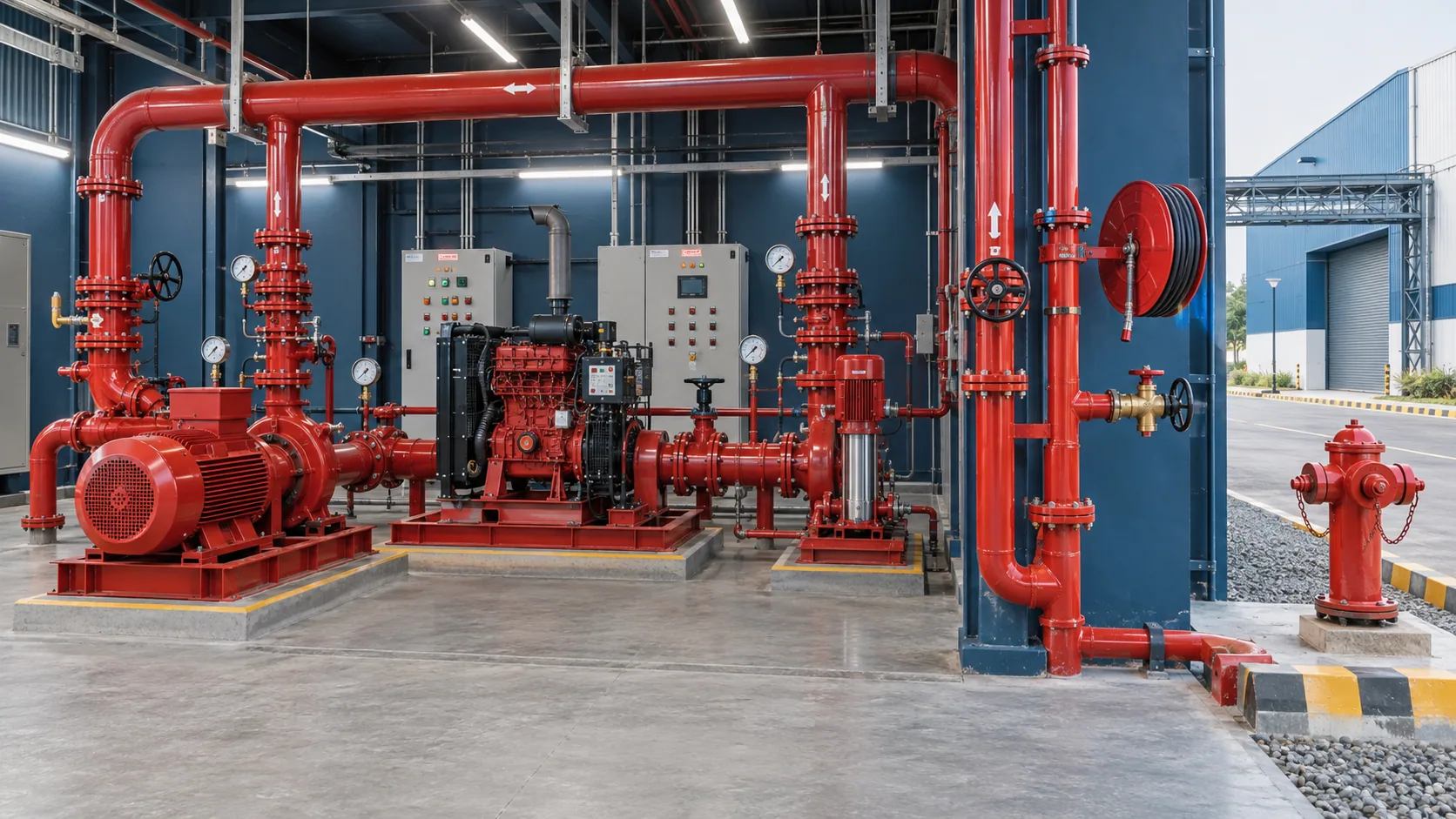
The pump room converts stored water into dependable system performance. Pump duty, suction conditions, redundancy, controllers, valves, test arrangements, drainage and access must work together at the required flow and pressure.
WHY IT MATTERS
Water-based systems depend on the pump room every time pressure falls or a fire demand occurs. Correct selection, installation and routine testing protect the performance of the complete hydrant and sprinkler network.
THE MERCURY STANDARD
Every decision remains connected to risk, performance, workmanship and long-term readiness.
Required flow, pressure and operating points are connected to the system demand.
Access, piping, controls, drainage and testing routes are coordinated for safe operation.
Automatic starting and pump performance are demonstrated and recorded under test.
A serviceable, tested pump installation that gives the protection network dependable hydraulic performance.
SYSTEM IN PRACTICE
Clear technical depth for project teams—organised around where the system applies, how Mercury develops it and how performance is protected after handover.
We establish the duty point, redundancy, suction conditions, controls and test arrangement required to make the fire-water network dependable at its remote demand.
ENGINEERING CONSIDERATIONS
MERCURY SCOPE
COMMON QUESTIONS
It maintains normal system pressure and prevents unnecessary starting of the main fire pump for small pressure variations.
Measured flow and pressure show whether the installed pump can still achieve its required operating duty.
Operators and service teams need safe access to controllers, valves, engines, motors and test points during inspection and emergency response.
NEXT STEP